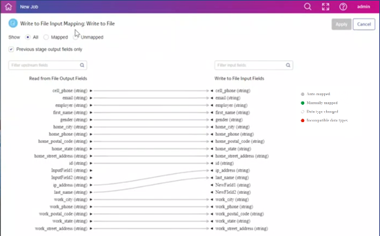
Mapping details page
Flow Designer displays mapping controls and status on the Mapping details page.
| Option | Description |
|---|---|
| Show | Filters the fields displayed:
|
| Previous stage output fields only | Controls whether the output field list contains only fields from the previous stage (default) or all upstream fields |
| Filter input field names | Depending on the display you selected, shows a filter field that displays names based on a string you enter here |
| Stage name Output fields | Lists the output fields upstream of this channel |
| Stage name Input fields | Lists the input fields of the next stage in the dataflow |
|
Mapping type 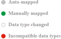
|
The mapping type is indicated by color or dashes. The legend on the page identifies channel colors and patterns.
|